Decoding the Smith Chart: A Complete Information to Impedance Matching
Associated Articles: Decoding the Smith Chart: A Complete Information to Impedance Matching
Introduction
With enthusiasm, let’s navigate by means of the intriguing matter associated to Decoding the Smith Chart: A Complete Information to Impedance Matching. Let’s weave attention-grabbing data and provide recent views to the readers.
Desk of Content material
Decoding the Smith Chart: A Complete Information to Impedance Matching

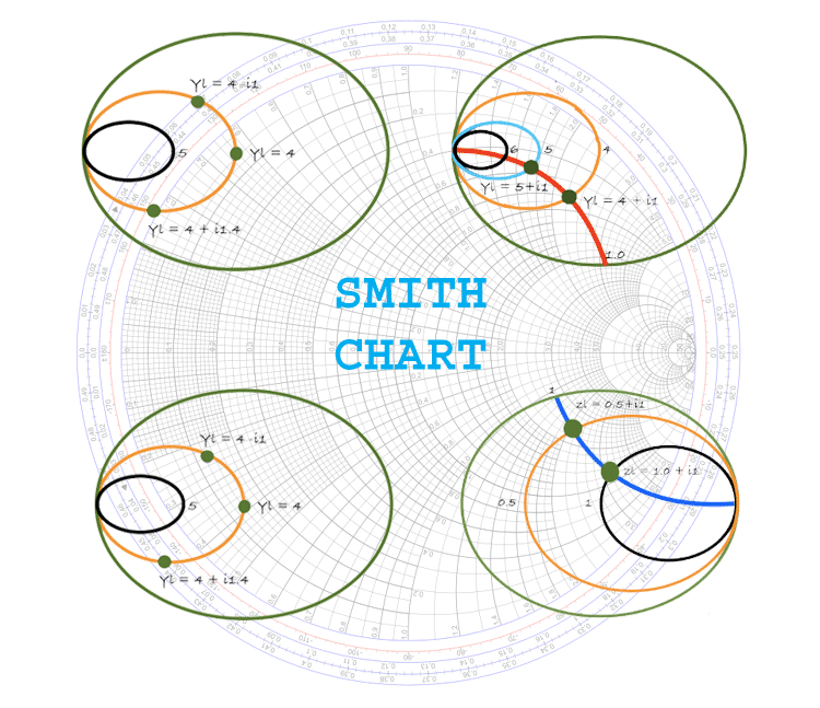
The Smith Chart, a ubiquitous device in radio frequency (RF) and microwave engineering, would possibly seem daunting at first look. Its round and seemingly advanced format belies its elegant simplicity and immense energy. This complete information will demystify the Smith Chart, explaining its development, purposes, and sensible utilization, in the end showcasing its indispensable position in impedance matching and circuit design. We’ll discover its theoretical underpinnings and delve into sensible examples, solidifying your understanding of this important device. Whereas a PDF model of this information might be generated, the next textual content gives an intensive exploration of the Smith Chart’s capabilities.
Understanding the Advanced Impedance Airplane:
Earlier than diving into the intricacies of the Smith Chart, we should first grasp the idea of advanced impedance. Impedance (Z) is the opposition to the circulate of alternating present (AC) and is represented as a fancy quantity:
Z = R + jX
the place:
- R represents the resistance (actual half), a measure of vitality dissipation.
- X represents the reactance (imaginary half), a measure of vitality storage in both inductive (optimistic X) or capacitive (adverse X) components.
- j is the imaginary unit (√-1).
The advanced impedance airplane is a graphical illustration the place the horizontal axis represents resistance (R) and the vertical axis represents reactance (X). Every level on this airplane uniquely defines a selected impedance worth. Nonetheless, this Cartesian illustration might be cumbersome for sure calculations, significantly these involving impedance transformations. That is the place the Smith Chart excels.
The Smith Chart: A Transformation to the Energy of Circles:
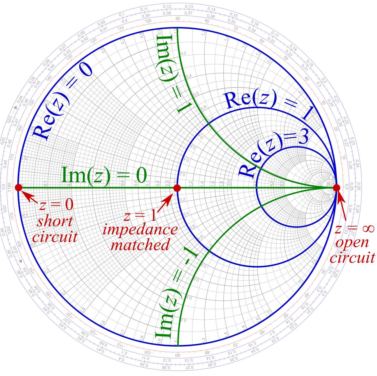
The Smith Chart cleverly transforms the advanced impedance airplane right into a normalized impedance airplane utilizing a conformal transformation. This transformation maps all doable impedance values onto a circle of unit radius. Normalization includes dividing the impedance by a attribute impedance (Z₀), sometimes 50 ohms in lots of RF programs. This normalization permits for a common utility of the chart whatever the system’s attribute impedance.
The normalized impedance is given by:
z = Z/Z₀ = r + jx
the place:
- z is the normalized impedance
- r is the normalized resistance (R/Z₀)
- x is the normalized reactance (X/Z₀)
The Smith Chart consists of two households of circles:
-
Fixed Resistance Circles (r-circles): These circles signify fixed values of normalized resistance (r). They’re centered on the horizontal axis (r=0) and their radii improve as r will increase. The outermost circle represents infinite resistance (r=∞).
-
Fixed Reactance Circles (x-circles): These circles signify fixed values of normalized reactance (x). They’re centered on the horizontal axis (r=1) and intersect the horizontal axis at r=1. The higher half-plane represents inductive reactance (x>0), whereas the decrease half-plane represents capacitive reactance (x<0).
Purposes of the Smith Chart:
The Smith Chart’s energy lies in its capacity to simplify advanced calculations associated to impedance matching, transmission line evaluation, and community synthesis. Some key purposes embrace:
-
Impedance Matching: That is maybe probably the most essential utility. The chart permits for fast and environment friendly willpower of the matching community elements required to match a load impedance to the attribute impedance of the transmission line, minimizing reflections and maximizing energy switch. This includes discovering the purpose representing the load impedance on the chart after which utilizing the circles to find out the suitable matching community elements (e.g., sequence/parallel capacitors or inductors).
-
Transmission Line Evaluation: The Smith Chart can be utilized to find out the enter impedance of a transmission line given its size and cargo impedance. Rotating across the chart by an angle proportional to {the electrical} size of the road (βl, the place β is the propagation fixed and l is the size) gives the enter impedance. That is significantly helpful for analyzing stub tuners and different transmission line matching strategies.
-
Stability Evaluation: The Smith Chart can be utilized to find out the steadiness of energetic RF circuits (e.g., amplifiers). By plotting the enter and output impedances, one can assess whether or not the circuit is unconditionally secure or requires stabilization strategies.
-
Community Synthesis: The Smith Chart aids in designing matching networks and different RF circuits by offering a visible illustration of impedance transformations. This enables engineers to intuitively select elements and configurations for optimum efficiency.
-
S-Parameter Evaluation: Whereas circuitously plotted on the chart, S-parameters (scattering parameters) might be simply interpreted and used at the side of the Smith Chart to research the efficiency of two-port networks.
Sensible Utilization and Examples:
Take into account a load impedance of ZL = 75 + j50 ohms linked to a 50-ohm transmission line. To match this load, we first normalize the impedance:
zL = ZL/Z₀ = (75 + j50)/50 = 1.5 + j1
We find this level (1.5, j1) on the Smith Chart. Then, utilizing the fixed resistance and reactance circles, we will decide the mandatory matching community elements. For example, we might add a sequence capacitor to cancel the reactive part after which a shunt inductor to regulate the resistance. The Smith Chart graphically illustrates the impedance transformation at every step.
One other sensible instance includes figuring out the enter impedance of a transmission line with a selected size and cargo impedance. By finding the load impedance on the chart and rotating alongside the fixed SWR circle by an angle similar to {the electrical} size of the road, we will instantly learn the enter impedance.
Benefits and Limitations:
The Smith Chart presents a number of benefits:
- Graphical Illustration: Offers a visible and intuitive understanding of impedance transformations.
- Simplicity: Simplifies advanced calculations that might be tedious utilizing algebraic strategies.
- Versatility: Relevant to a variety of RF and microwave purposes.
Nonetheless, it additionally has limitations:
- Approximations: Graphical options are inherently approximate.
- Restricted Accuracy: The accuracy is restricted by the precision of the chart and the person’s capacity to learn it precisely.
- Steeper Studying Curve: Requires a strong understanding of advanced impedance and transmission line principle.
Conclusion:
The Smith Chart, regardless of its seemingly advanced look, is a useful device for RF and microwave engineers. Its capacity to visually signify impedance transformations and simplify advanced calculations makes it indispensable for impedance matching, transmission line evaluation, and community synthesis. Whereas mastering its use requires devoted effort, the rewards are substantial, enabling environment friendly and efficient design of high-frequency circuits. This information gives a strong basis for understanding and successfully using this highly effective device, encouraging additional exploration and sensible utility within the fascinating world of RF engineering. Whereas a printed PDF can be a handy reference, the great nature of this textual content ensures an intensive understanding of the Smith Chart’s capabilities.


Closure
Thus, we hope this text has supplied invaluable insights into Decoding the Smith Chart: A Complete Information to Impedance Matching. We hope you discover this text informative and useful. See you in our subsequent article!